Frame Design
This part of the project seemed fairly straightforward before I began. I figured about 4 weeks for design and stress simulation and another 4 weeks for fabrication. HA! The my actual time investment was 2.5 times higher than I anticipated. The quality and quantity of the engineering necessary was also much higher. My favorite issues during the process were:
- I decided to use the IRS Subframe from a 2004 Ford Cobra. The subframe seemed like a good idea (and maybe it is) but it made routing the frame over the rear axle nearly impossible.
- Tube Bending. I could not get any fabrication shops to bend the rectangular tubing to my specs for anything less than a King's ransom. The folks at Art Morrison were good to communicate with, but they were not set up for the compound, close bends required. he only vendor willing to sign up was a high end shop in Southern California who wanted a bit over $7,000. I ended up redesigning the frame three times to attempt to accommodate. I finally gave up and figured out how to "bend" rectangular tube myself (more on that later).
- I've designed some pretty extreme structure in the past (check out www.pix2o.com for some of them). I've often used waterjet cut plates with slots and tabs to maintain tolerance as the structure is assembled. This frame was designed the same way, however getting the plates cut here on Northern California was just painful. I literally wasted a month finding someone who would cut a large number of individual plates for a single project. Since then, I've found a good source, but I wasted a lot of time.
- Because I do not have a full scale jig to assembly the frame, I spent a bunch of time balancing welds and setting up reference points to hold the frame in alignment as it was assembled.
Why did I think this was a good idea? (and still do...)
My goals were:
- Install an Independent Rear Suspension.
- Install rack and pinion steering with no bump steer.
- Install Modern front suspension geometry (scrub, scrub radius, camber gain, brakes, ABS, etc)
- Relocate the engine rearward for better balance and to clear the steering rack (the car is now a front-mid engine, as a Corvette)
- Lower the engine for better handling.
- Set the frame lower (at nominal suspension geometry) for better handling.
- Stiffen the frame considerably over the stock offering to improve handling. I achieved and increase of about 10x in lateral stiffness in the front and well over 10x increase in torsional rigidity.
- Utilize wider front and rear tires.
Where to Begin??
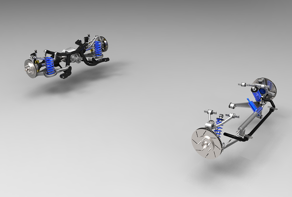
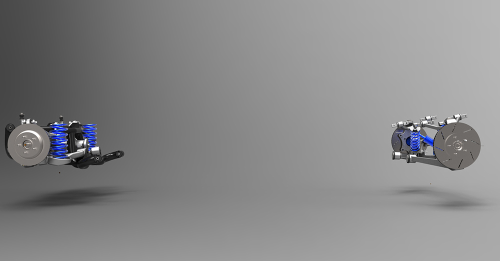
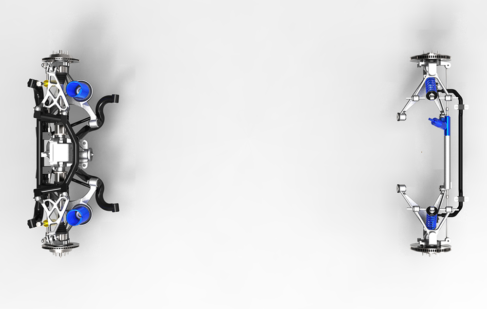
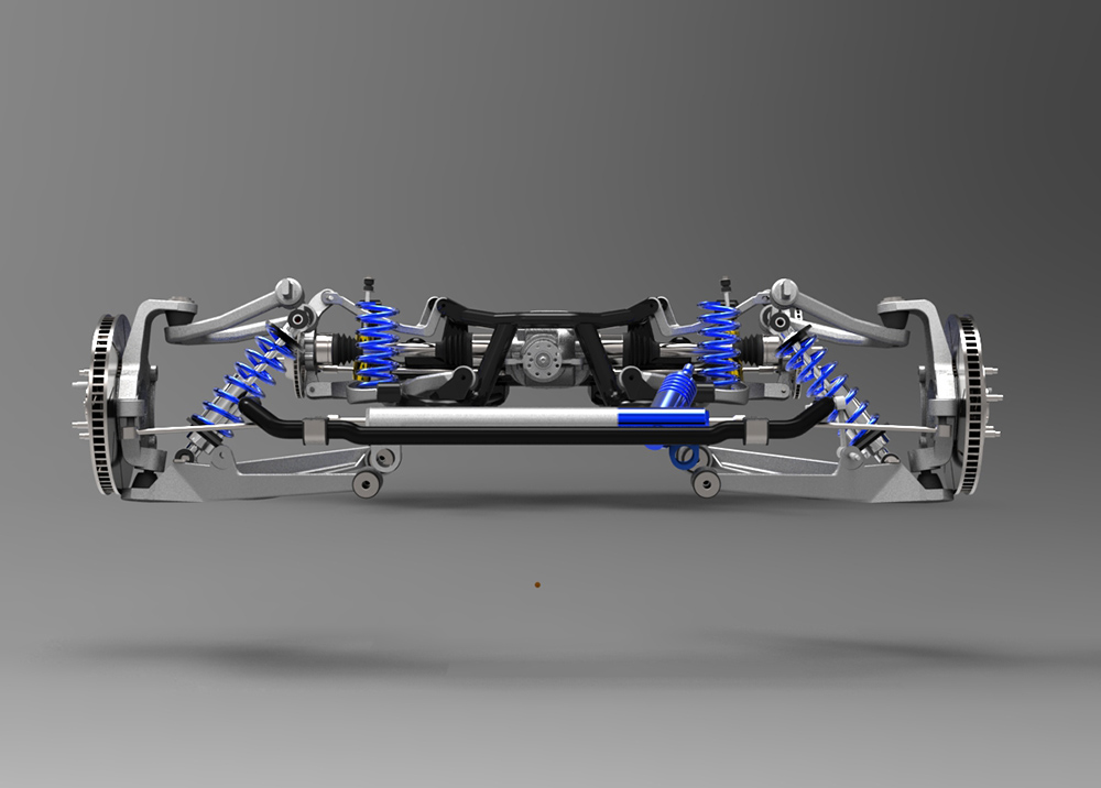
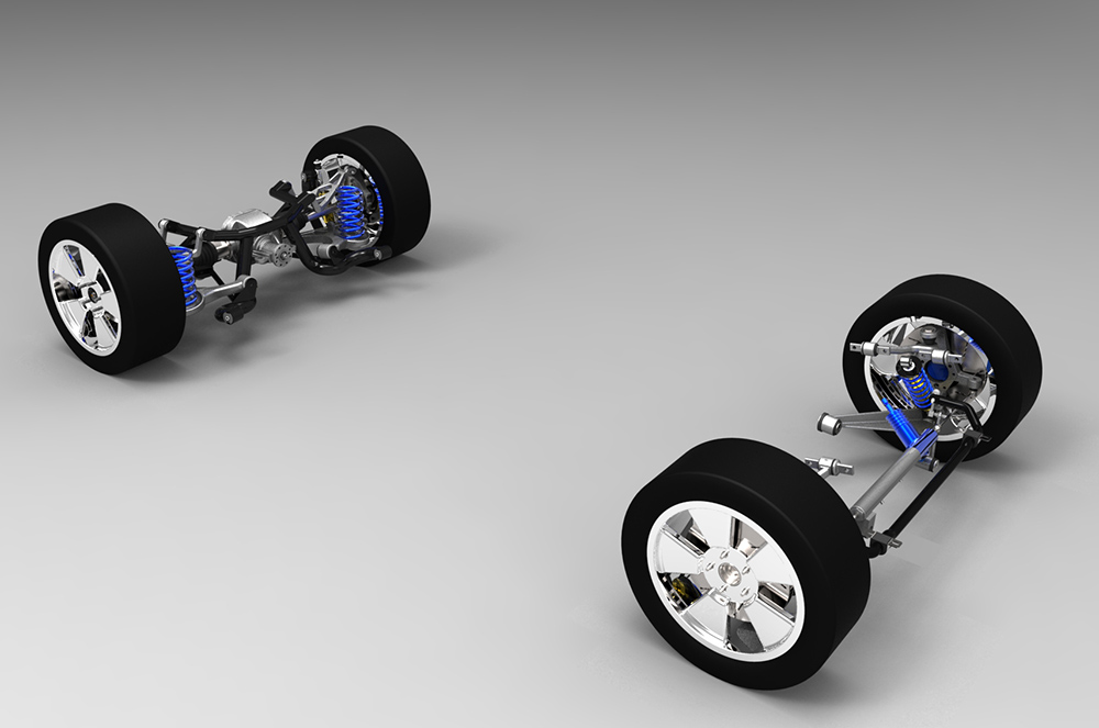
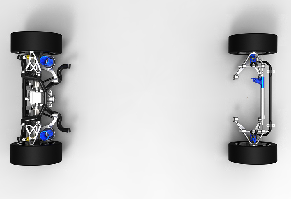
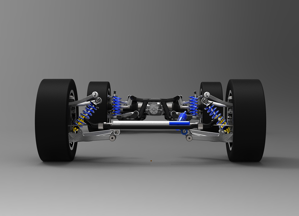
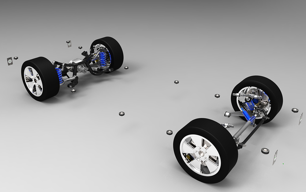
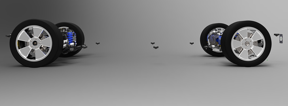
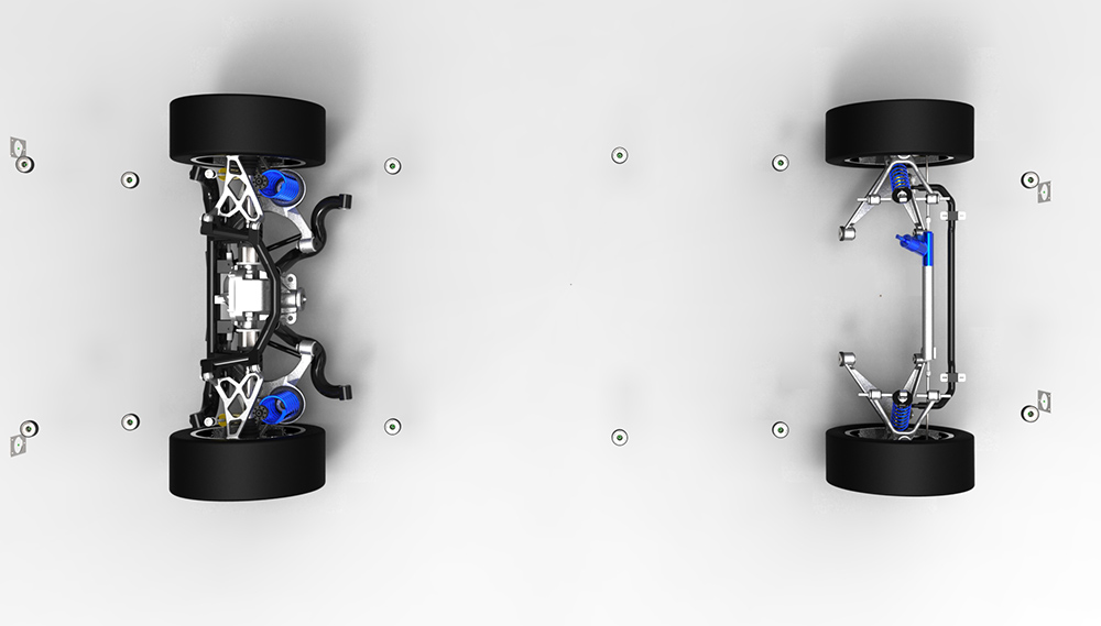
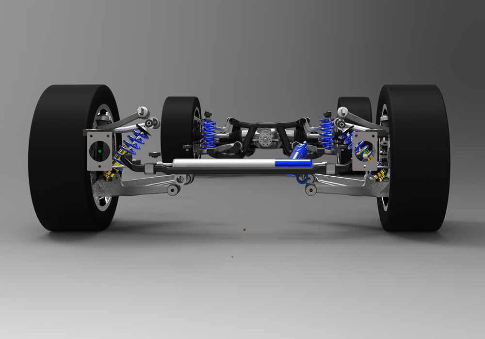
Before beginning on the frame itself, I set the front and rear suspension mounting points using Performance Trends software. The resulting performance is reviewed in the suspension section, the mounting points were transferred into the 3D solids modeling software and the front and rear suspensions were "built" and located relative to each other.
To this drawing the wheels/tires were "installed" and set on the ground. You may note that the rear wheels are slightly below ground. This was done to create about 3/4" of rake on the finished car while keeping the frame parallel to the ground for modeling purposes.
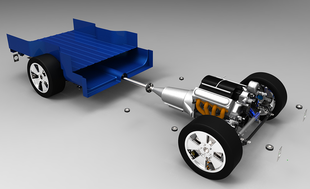
By taking careful measurements off of both the original frame and the El Camino's body, I build a 3D model of the locations of all of the body mounts. This model was then overlaid onto the suspension model. Side to side alignment of the body mount model was straightforward. The body mount information also defined the locations of the front and rear tire centerlines, so fore/aft alignment was also straightforward. Setting the height was based on my preference of how much I wanted to lower the body and how much ground clearance I wanted. One of the advantages of a custom frame is that I can set the body height wherever I wish while maintaining the suspension at it's optimal height. I decided to drop the car about 3" in front and 2-1/2" in the rear. After this alignment with the Suspension and Tire model, the composite model is what you see below.
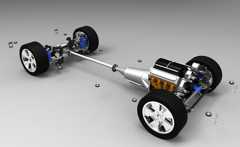
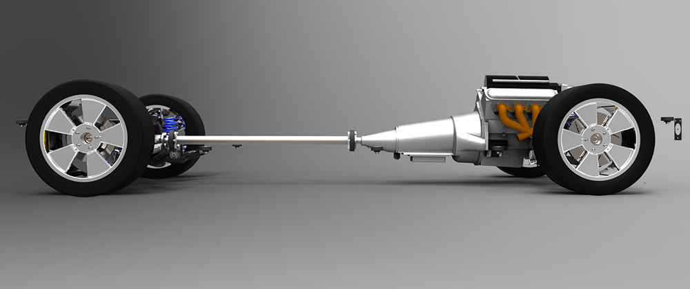
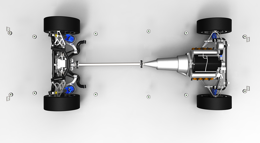
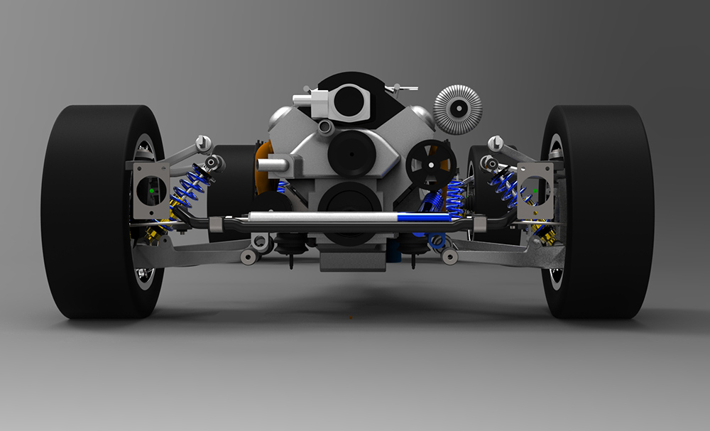
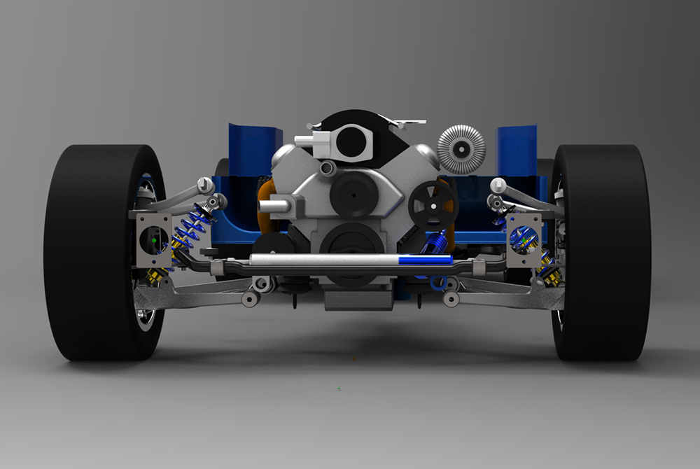
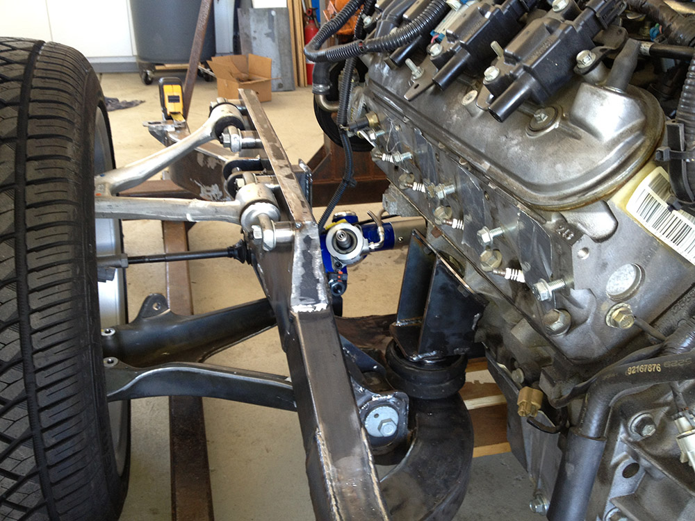
The next step was to integrate the drivetrain. For the LS2 model, I started with a crude 3D model someone had shared on grabcad, improved the accuracy and added the appropriate accessories (trans, mounts, balancer, pump, alternator, exhaust manifolds, etc). The engine was aligned to the centerline of the suspension. There are some advantages to slightly offset the engine, however in this application I was quite limited as the GTO floor pan transmission tunnel is offset toward the driver's side (remember the GTO was originally a right hand drive car) but the input shaft of the rear differential is offset to the passenger side of the chassis. Fore/aft alignment was easy. I moved it as far forward as I could. As part of this project, I converted the harmonic balancer to a corvette unit which is about 3/4" shallower than the GTO/Camaro balancer. The balancer was placed a bit over 3/8" behind the steering rack. It's tight, but there is enough room to replace a drive belt. To remove the balancer, it will be necessary to remove the steering rack but I've designed that to be pretty easy. The final step was to set the engine height. I decided (somewhat arbitrarily) that I wanted the minimum clearance to be 4" under the engine. Because I will be protecting the oil pan with a skid plate, I set the bottom of the oil pan to be 4-1/2" off the ground. Though I will cover it a bit more elsewhere, I decided to use the stock biscuit style engine mounts. Unfortunately, the stock brackets would have caused the motor mount to interfere with the lower control arm bushing, so I designed and fabricated the engine mounted brackets. As you can see form the renderings below, the engine is completely behing the centerline of the engine
Because of all of the routing necessary to fit the IRS and it's subframe, I decided that I needed to create a model of the rear underside of the body to verify clearance or confirm interference that I will need to address.
By this point, the model pretty much defines all the frame connection points and the allowable routing zones in the more congested areas. Now I could begin the design process for the frame. The frame was designed using bent rectangular tubing (2x4,0.120" wall for the primary rails, 2x3, 0.120" wall for secondary ones) and flat, waterjet cut, plates for mounting points and stiffeners. In order for me to maintain a tight tolerance on the assembled frame, the tubing needed to be bent more accurately than all but one vendor would sign up to. That vendor wanted over $3K to bend the tubes. That was twice the expected cost of the entire frame project, so I fabricated some simple tools to allow me to "bend" tubes in my shop. Aside from underestimating the amount of time necessary to "bend" a tube, the results exceeded my expectations. I was able to hold the angles to +/- 0.2 degrees tolerance and maintain the straight sections to within 1mm of design.
In keeping with sound design practices, I spent a bit of time on the web studying frame designs from reputable shops looking for ideas that I could steal and incorporate. I did find some very good ideas to steal and saw some really interesting examples of bad design and engineering. Not surprisingly, there are some folks out there selling frames that are overstressed in the engineering sense (they might not break today, but they will begin to yield and will fail in a relatively short period.) Many of the custom frames that I saw heavily utilized round tubing. While I have done structural work with round tubing, I have no experience (or equipment) bending round tubing, so I shied away from those designs.
As I designed the frame, I broke it down into front and rear subframes connected by center rails. This made the design a bit easier.
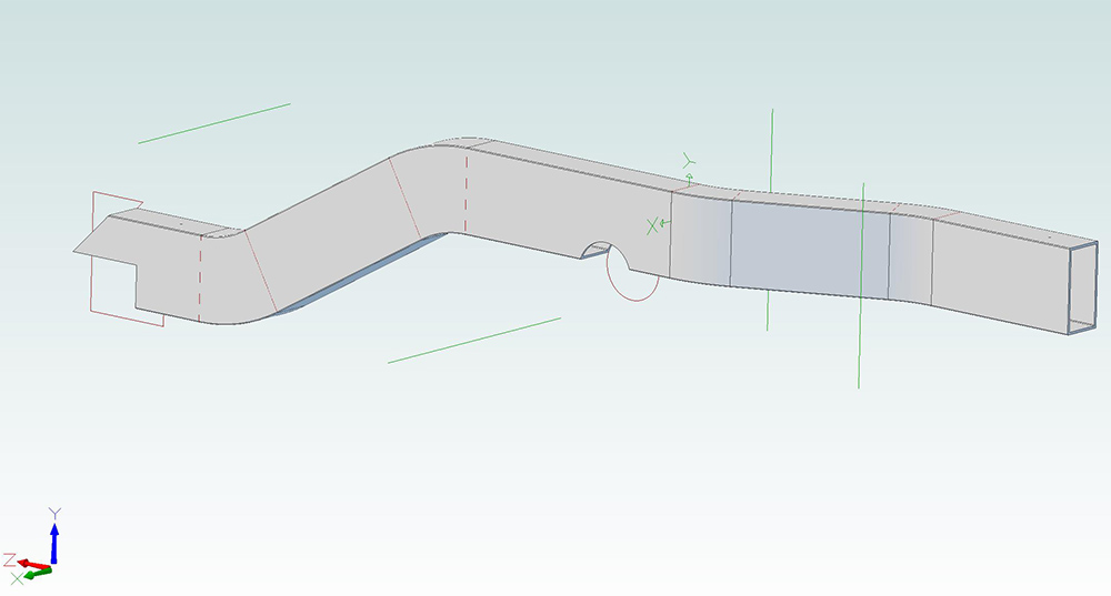
Taking a close look at the front subframe design, I started with the front frame rails and routed them in the available space. Given that the engine mounts and suspension points are defined as well as the body and bumper mounts, there are not that many routing options. The left front frame rail is shown below:
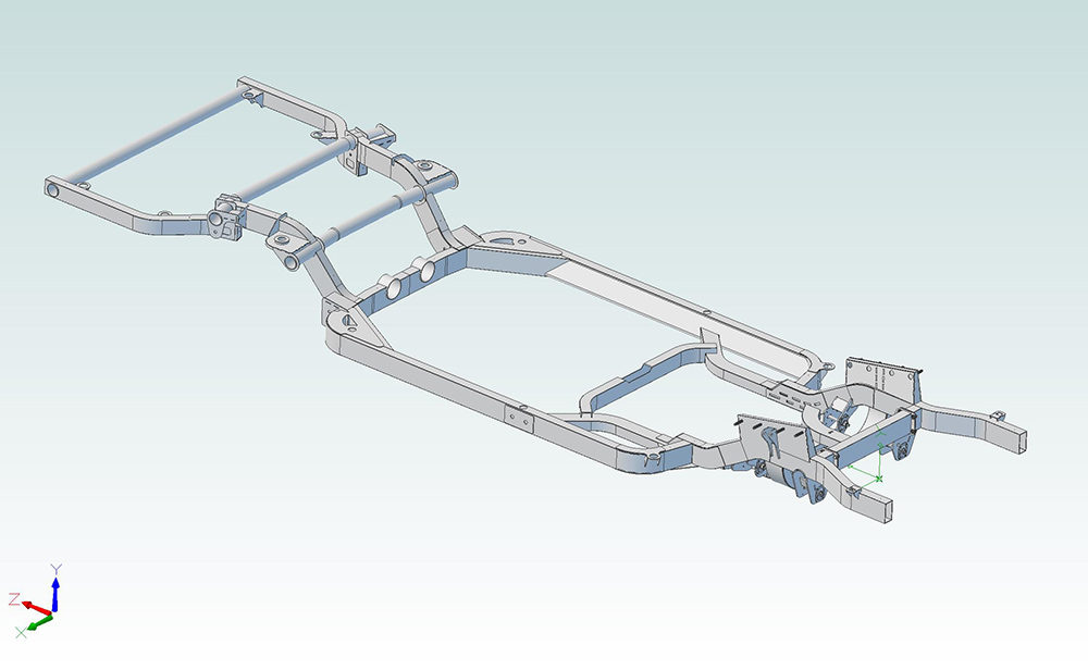
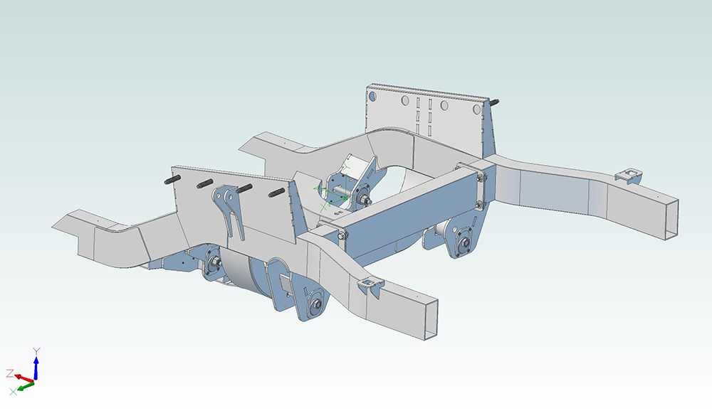
The rear subframe and center framerails were designed and integrated in a similar fashion. Finally the frame was assembled in the model. The results are shown below:
The links above should open a dimensional drawing and a 3D drawing of the frame rail. If you click inside the window, the 3D drawing can be zoomed and rotated in space using the mouse and control wheel to observe the object from all angles. You will need to use the back arrow in the browser to get back to this page when you are done. Unfortunately these links don't work properly on a Mac. I'm not sure why, but it's on my list to fix.
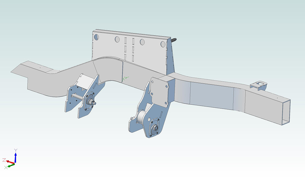
To the frame rail, I added the necessary mounting points for the suspension. The result is shown below:
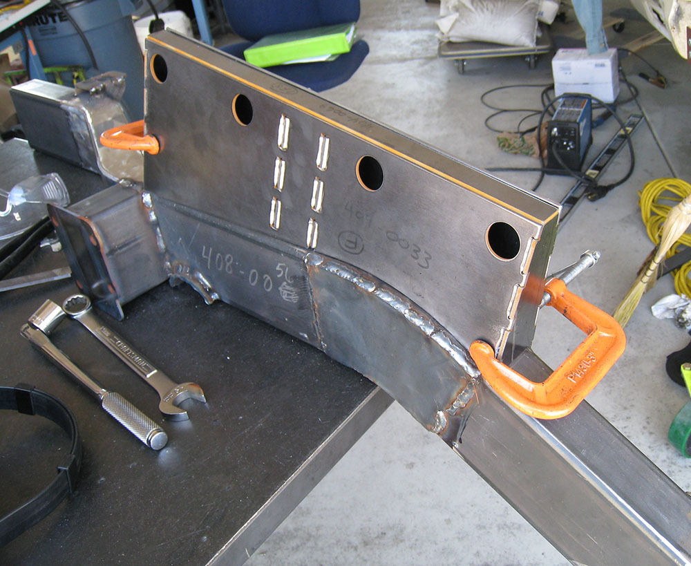
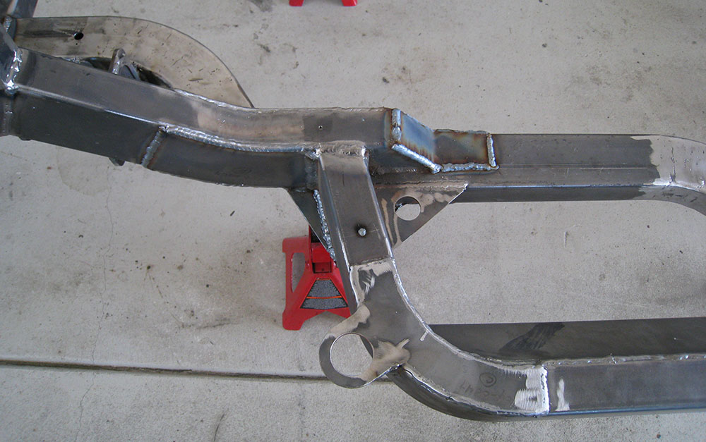
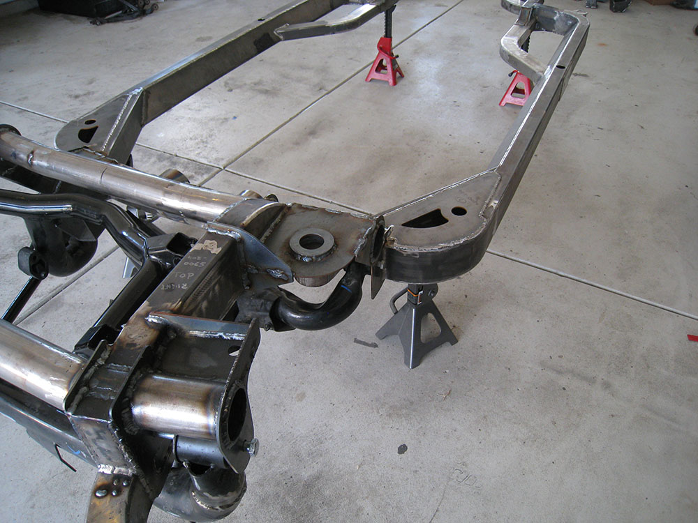
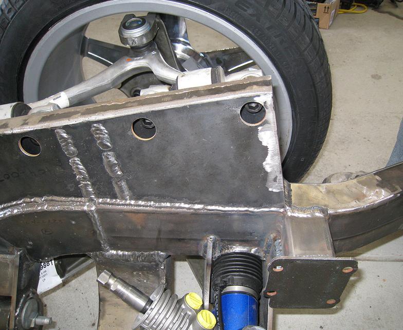
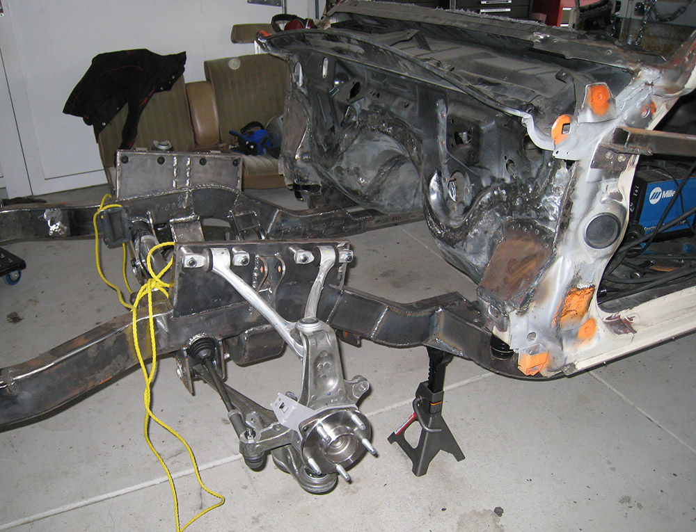
As you can probably see from the drawings, the design is basically comprised of bent rectangular tubes and flat plates welded together. Further, the plates utilize slots and tabs for alignment during assembly. Coupled with accurate drawings, I was able to assembly the frame to within 1mm tolerance without the use of a jig.
This is demonstrated in the photo below:
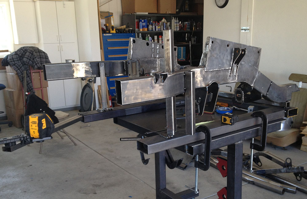
Accurate assembly of this sub-section was straightforward, requiring a flat table, clamps and a laser cross level as shown in the picture below:
Continuing with the design, the front frame rails were then assembled into the subframe shown below:
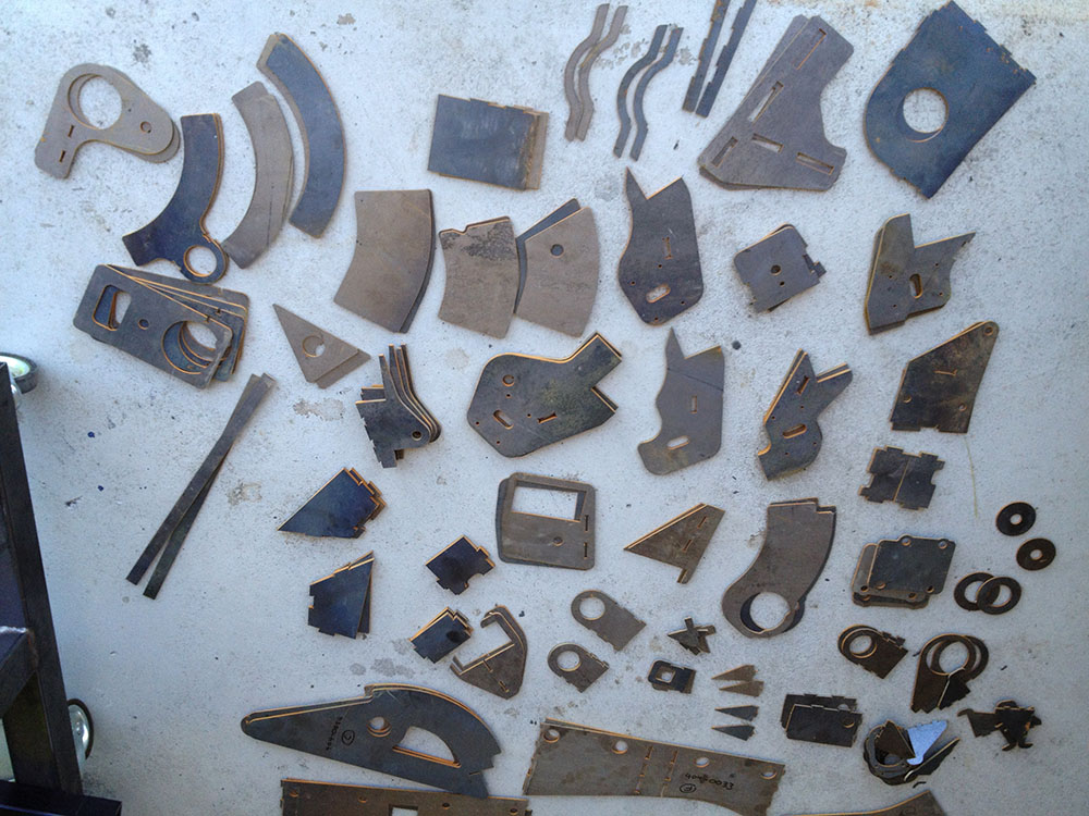
Below is a picture of many of the plates used in the frame as they were received from the waterjet shop:
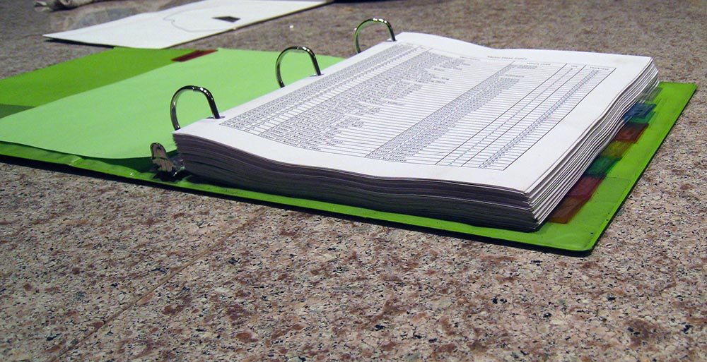
On a related topic, below is a picture of the stack of component and assembly documentation representing the frame design:
During this phase of the CAD design process, the frame was subjected to FEA stress analysis. Finite Element Analysis is a process where the stresses and deflections of a structure can be simulated under applied loads. It's a very powerful tool during the development process. The cost of these tools has dropped significantly over the years and the tools have become much more user friendly. However, it was still a $2000 upgrade to my 3D CAD package and was a pain to use. To avoid buying the tool, I completed all analysis work during the 15 day evaluation period. I never did get the printing tools to work well, so while I did collect the numbers and have a really good handle on the stresses and deflections, I don't have any pretty pictures for this phase.
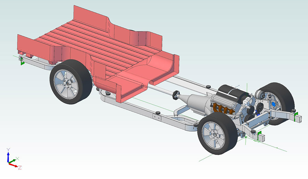
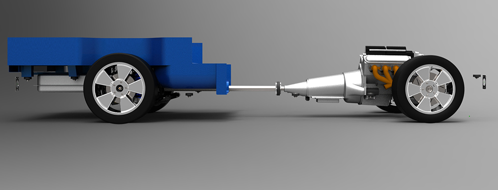
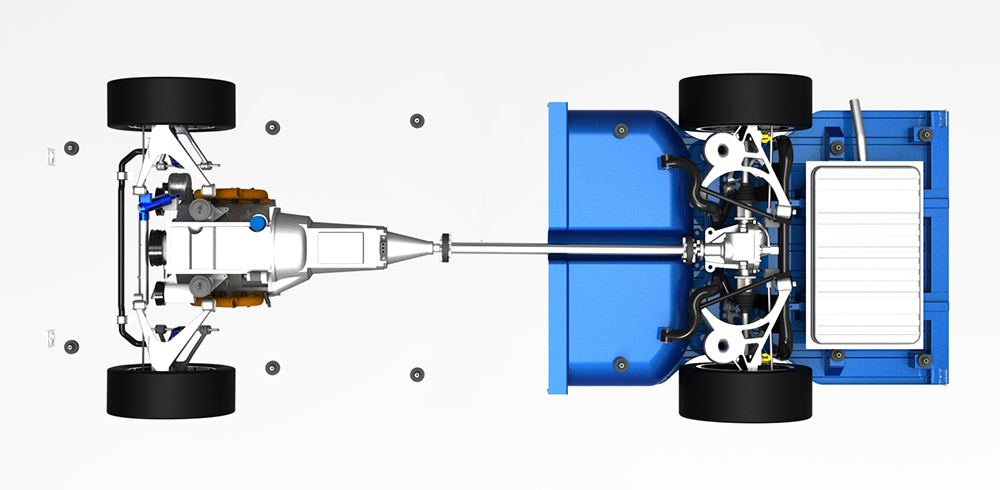
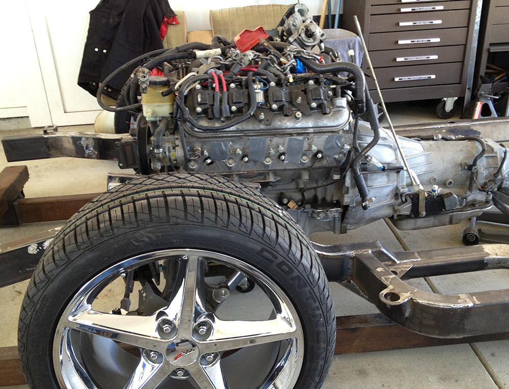
The frame was then integrated with the suspension, drivetrain and body:
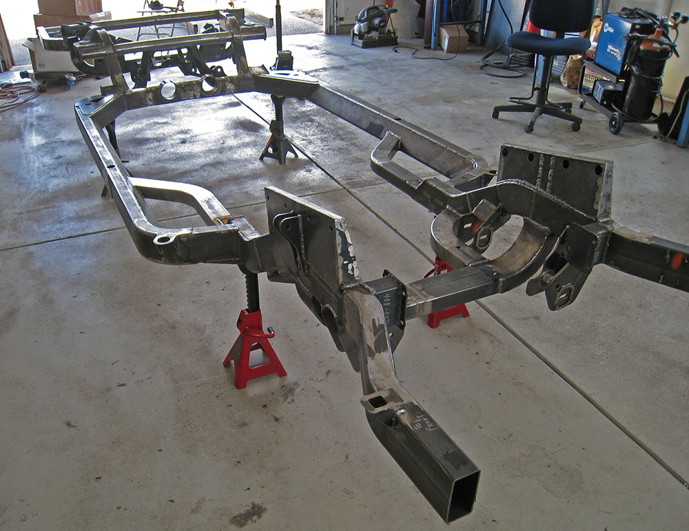
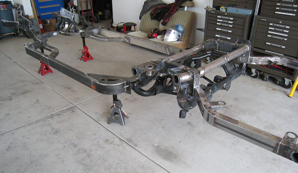
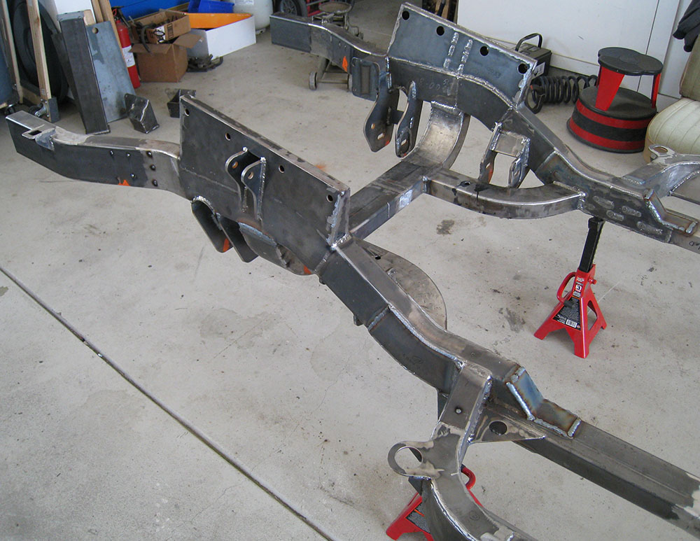
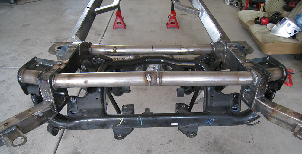
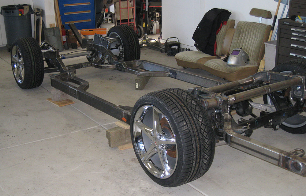
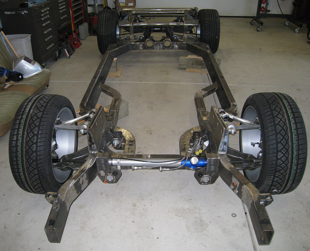
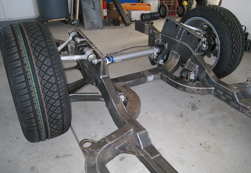
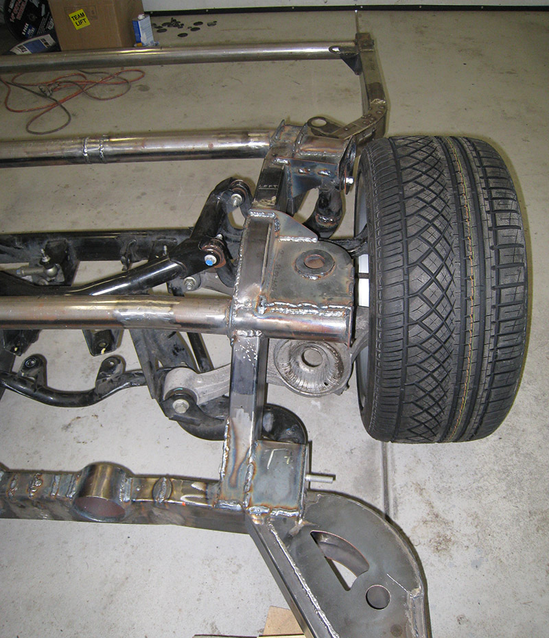
And some pictures of the assembled frame:
Warning: 13MB file
Copyright 2014, Leo Stearns