Front Suspension
As I investigated upgrading the front suspension and brakes, the primary objectives were to improve:
- Kore3 hubs, coupled with late B-body spindles (equipped with speed sensor mounts).
- AFX spindles, which used C5 hubs.
- C5/C6 front suspension.
The first requirement pretty much forces C5/C6 front brakes along with 48 tooth wheel sensors to align the performance with the ABS system out of the '06 GTO. This limited my choices to three:
- Braking; ABS coupled with larger brakes.
- Handling; improved steering and suspension geometries.
- Steering Feel.
Below is a quick summary of the advantages and drawbacks of each.
Kore3:
In the Positive ledger:
- Taller spindles eliminate the positive camber under slight compression issue exhibited by stock suspensions.
- Taller spindles move the instant roll center above ground (assuming stock ride height.)
- Most other suspension geometries are unchanged from stock. Including significant positive camber at higher steering angles.
- Because the steering arm on the B-body spindle is located lower than the G-body spindle, Bump steer is made worse.
- The B-Body ABS reluctor ring is 34 teeth. Given the size of the sensor, it's not clear that a custom 48 tooth ring would function properly. So, the best solution I identified was fabricating a 24 tooth ring and designing a pulse doubler circuit which would trigger off of the leading and trailing edges of each tooth.
- I've read about concerns with the length of the steering arm as well as the net Ackerman angle, but I've measured both stock and B-body spindles and don't see these differences as meaningful.
- If the car is dropped using shorter springs, the instantaneous roll center can move back below ground.
ATX:
In the Positive ledger:
In the Negative ledger:
- Taller spindles eliminate the positive camber under slight compression issue exhibited by stock suspensions.
- Taller spindles move the instant roll center above ground (assuming stock ride height.)
- The use of C5 hubs translated to 48 tooth, sealed stock ABS sensors.
- Relocated steering arm, minimizing the bump steer issue with the stock suspension.
- Most other suspension geometries are unchanged from stock. Including significant positive camber at higher steering angles.
- If the car is dropped using shorter springs, the instantaneous roll center can move back below ground.
- Assuming they bump steer is not made even worse, this solution is not compatible with rack and pinion steering units. Lee and DSE steering boxes are probably an improvement over OE, but they are not going to offer the same feel as a rack.
- The most expensive possible solution in my case.
C5/C6:
In the Positive ledger:
In the Negative ledger:
- The suspension and steering geometries can be as correct as a C6 corvette.
- Select geometries can be customized around this application as the mounting points are designed.
- It's the lowest cost option (assuming I ignore the small matter of needing a new frame)
- I can easily use a rack and pinion steering unit.
- Engine can be mounted lower in chassis because frame rails are further apart. Engine will need to be located aft of the stock position to accommodate the steering and this can be accommodated on this project (see floorpan page).
- A complete front frame assembly will need to be designed to accommodate. In reality, that is not all that expensive. This will also allow me to greatly reduce the amount of frame flex.
- The C5/C6 suspension has milder camber curves than the stock suspension. Because I will be running wider tires than stock and wider tires require less camber, I'm not sure this is an issue.
Cost Analysis:
By my estimates the cost of the completed suspensions for either the Kore3 or C5/C6 are about the same. I am assuming all brand new GM parts for the C5/C6 solution. In comparison, the AFX solution appears to be approximately $2,200 more than the C5/C6. Considering that it only addresses some of the geometry and steering issues, it's not a good value to me. Reality is that if ignore my design and fabrication time, a new frame should cost approximately $1,000. Since I am not doing this project commercially, I can ignore my time. A detailed breakdown of my cost assumptions are below. Double click on the thumbnails for a larger image.
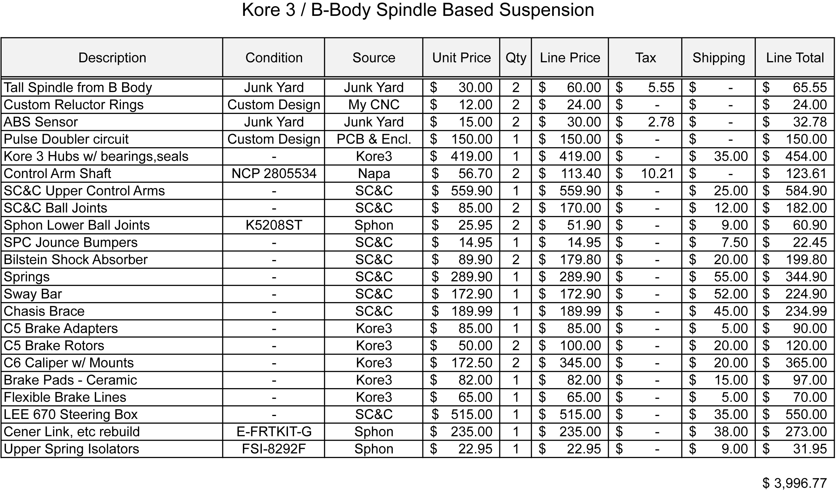
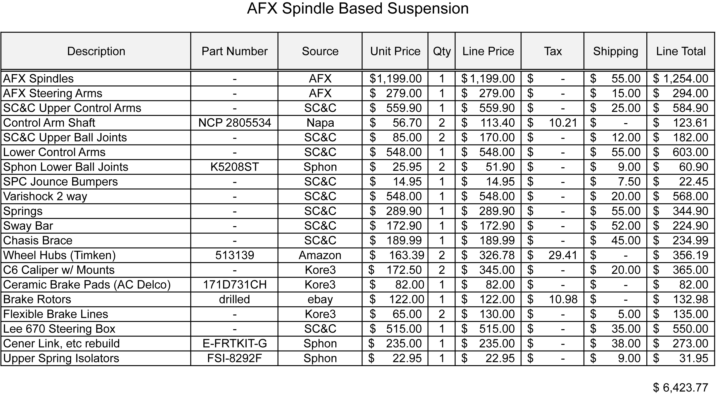
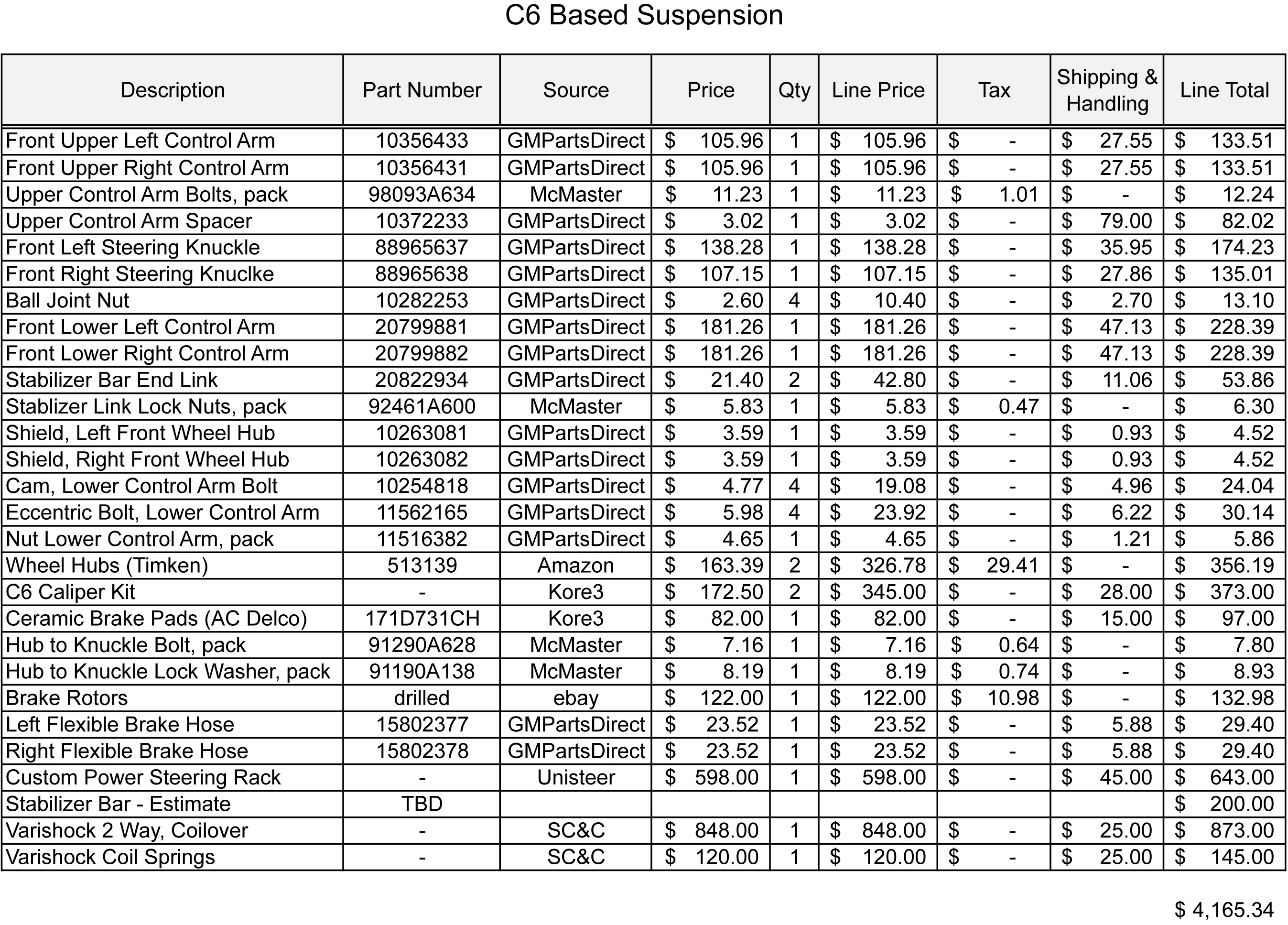
Based on my analysis and my level of comfort designing and fabricating a frame, I am going to use a C5/C6 based front suspension.
Kore3 AFX C5/C6
Copyright 2014, Leo Stearns
Now that the chassis and suspension design and fabrication are complete, it's a good time to review how I implemented the front suspension and compare it to my assumptions.
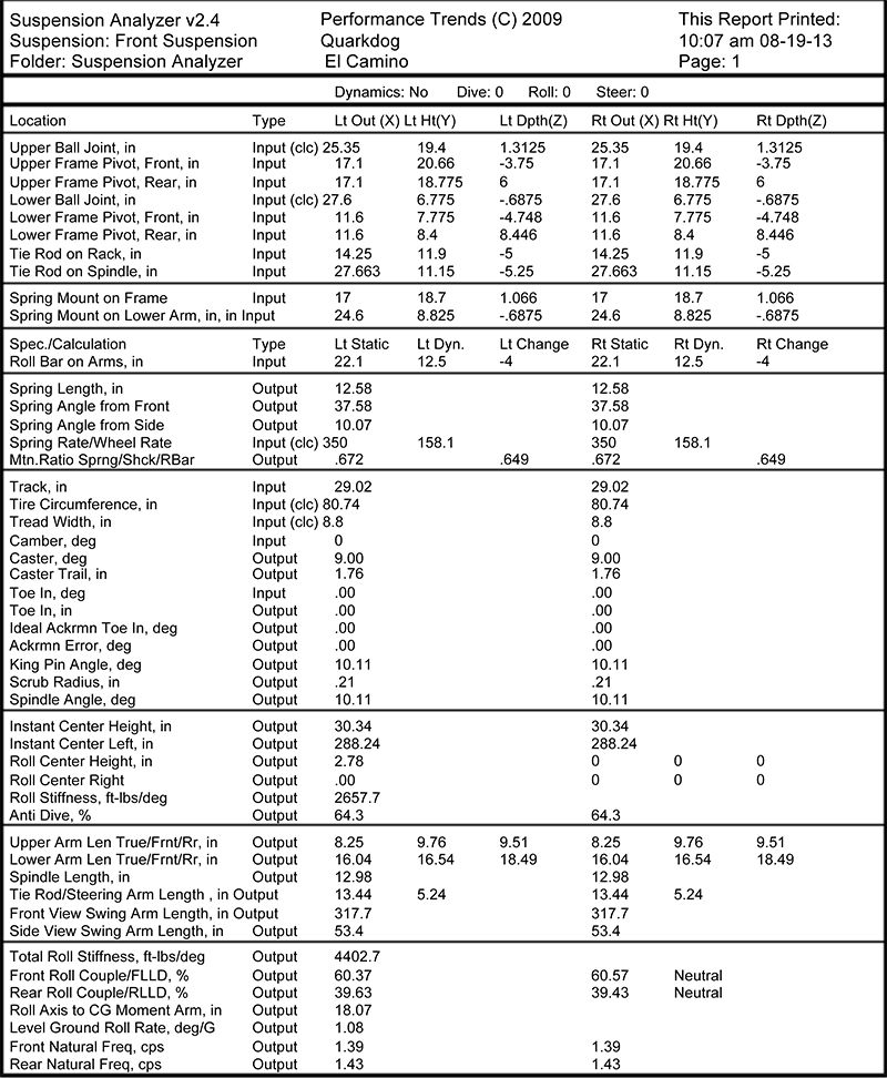
My first step in the implementation phase was to define the suspension mounting points in Performance Trend's Suspension Analyzer software. Included with the software is suspension configurations for several vehicles including the C5 Corvette. After confirming that the provided model actually match a physical Corvette, I set about to modify the suspension related pick up points for use on my El Camino.
The primary changes I needed to make to the Corvette suspension were:
- Narrow the front track by 3.0" to accommodate the El Camino's narrower body. This was simply a matter of moving all of the mounting points 1.5" closer to the car's centerline.
- Increase the height of the Longitudinal roll center to increase the % anti dive of the geometry. This was accomplished by rotating the lower control arm by approximately 3 degrees (raise the rear and lower the front while not moving the ball joint). The final anti-dive % is slightly more than the baseline Corvette.
- Slight increase in camber gain. This was accomplished by lowering the upper control arm pivot points, while holding the upper ball joint stationary. I really debated increasing the camber gain at all because it also increases the amount of tire scrub (scrub is NOT scrub radius) which causes the vehicle to wander as it drives down a bumpy road. Ultimately, I decided to slightly increase the gain to compensate for the increased body roll that the El Camino will experience compared the baseline Corvette (there is more discussion about these relationships in my suspension primer section {if I ever complete it})
- Relocate the spring from a transverse leaf spring to coil over shocks. Sourcing adequate coil over units is proving to be more problematic than I anticipated and I'm having second thoughts about this. I might end up modifying the engine crossmember and designing a custom leaf spring.
- Reduce the wheel rate about 25% over the baseline Corvette to smoothen the ride.
- Design an antisway bar and end links to mount to the custom frame and increase the roll rate to compensate for the higher CG of the El Camino.
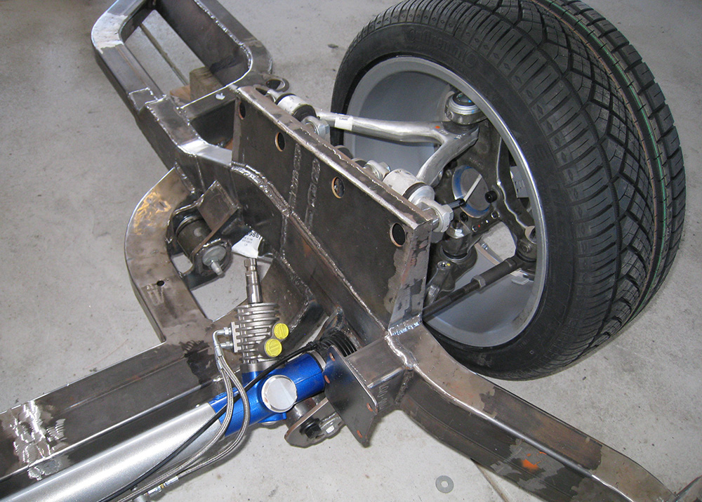
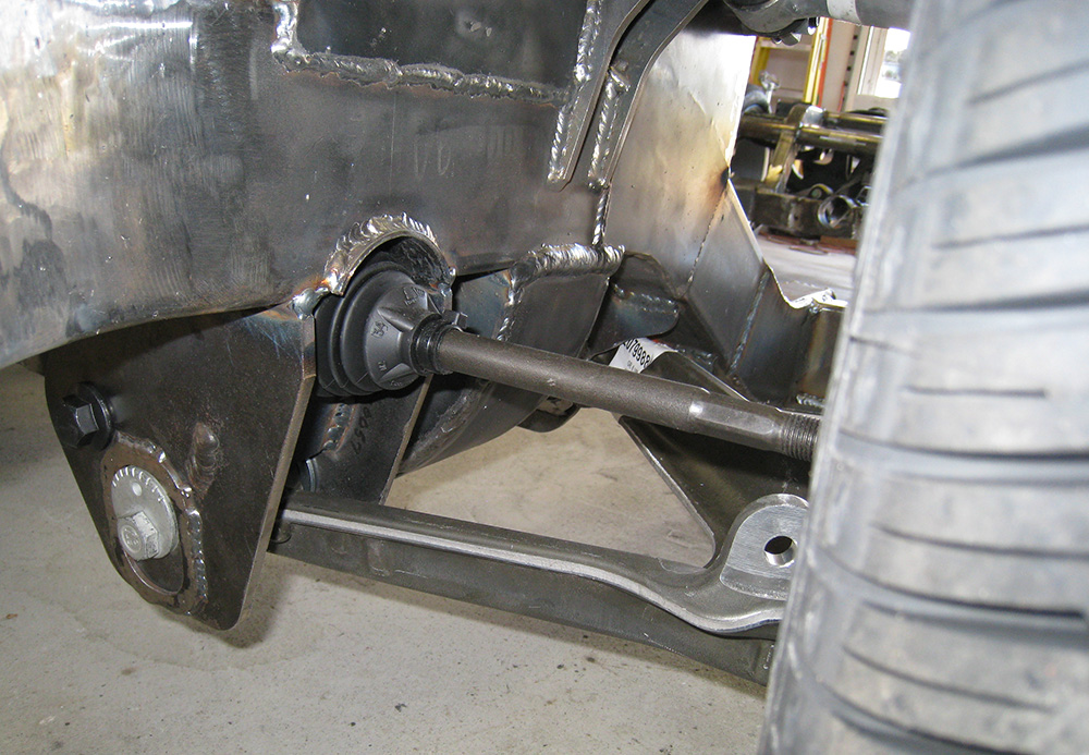
- Sourced a steering rack which is almost exactly 3" narrower than the stock Corvette unit, but offering the same amount of travel. The XL front steer unit from Flaming River is about perfect for this application. It is available with M14 inner tie rod threads which interface directly with standard C5 outer tie rod ends with about 1.75" of thread overlap.
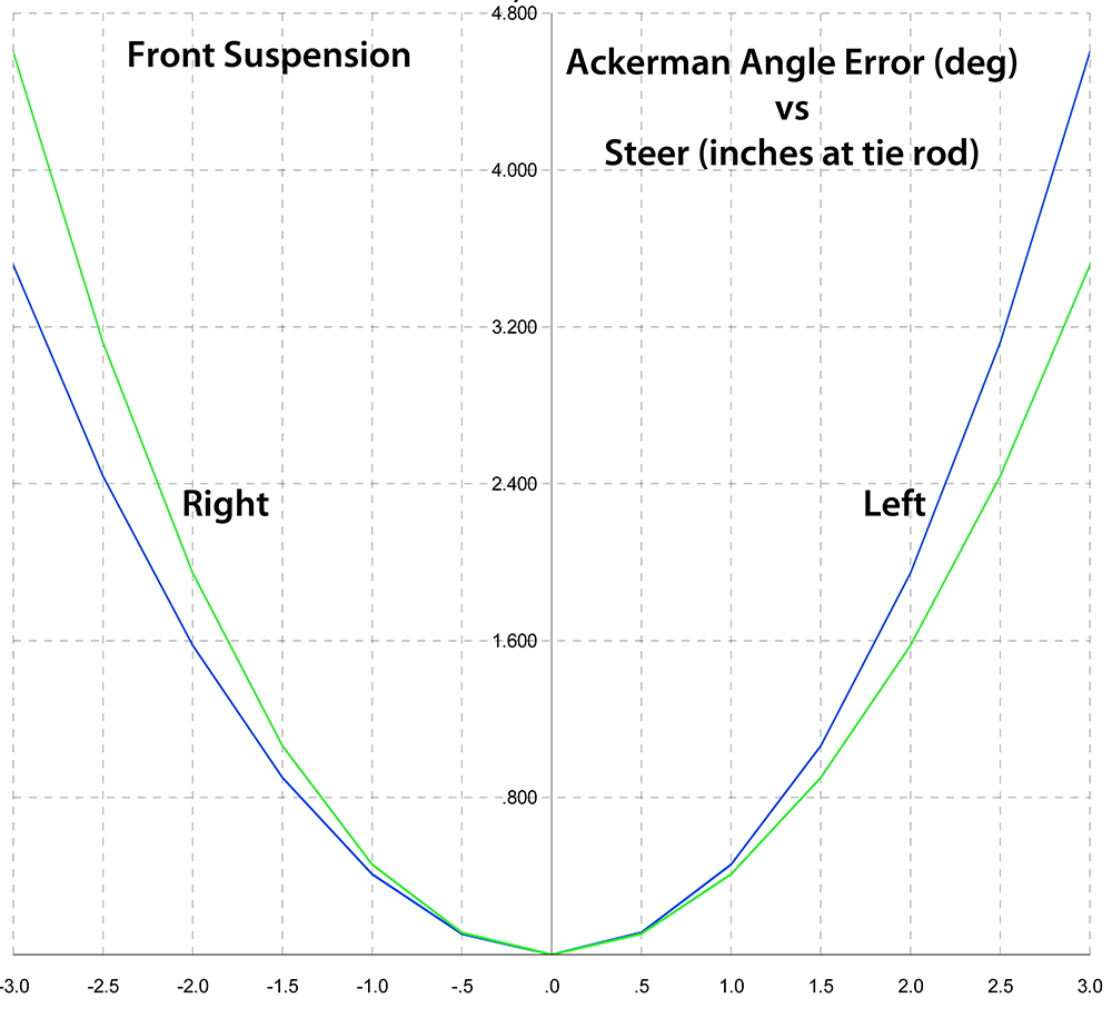
- Slightly relocated the steering rack to clear the front lower control arm pivot. The net result of this is that I virtually eliminated ANY bumpsteer, however I increased the Corvette's Ackerman angle error by a couple percent. Seeing as I don't race in parking lots, I see this as a good compromise.
- Moved the front wheel centers forward by 1.0" to provide a bit more clearance for the engine. This will fit the fender well because the Corvette suspension has a scrub radius of about 1/4" and, as a result, the wheels move fore/aft much less than the stock El Camino as the wheels are turned.
Once the suspension locating points were defined, the performance of the suspension was calculated in the Performance Trends software. After a bit of tweaking and tuning, the final design specs and calculated performance results are shown below. Notable points are:
- The car should exhibit neutral handling. I can force it to moderate understeer by changing out a sway bar.
- The body roll rate is approximately 1 degree per G, so body roll will be minimal.
- The effective swing arm length (front view) is approximately 318" which, coupled with the Roll Center Height of 2-3/4" will result in minimal scrub over bumpy roads. The effective swing arm length remains over 250" through expected suspension travel.
- The scrub radius is less than 1/4" which will minimize torque steer caused by brake imbalance or the engagement of ABS, while maintaining sufficient offset to not produce wander.
- There is an issue with the front and rear natural suspension frequencies. To create a flat response at 60mph, either the front rate needs to be 1.23hz or the rear 1.63hz. I am going to wait until I build and drive the car to determine if I want to go with 1.23/1.43 or 1.39/1.63. Once I figure that out, I will finalize the design of the rear sway bar to re-balance the handling.
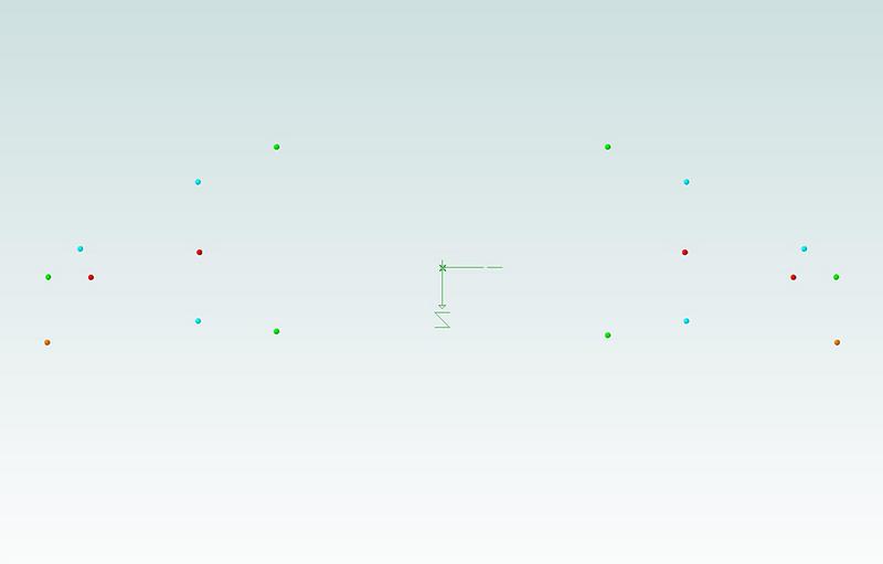
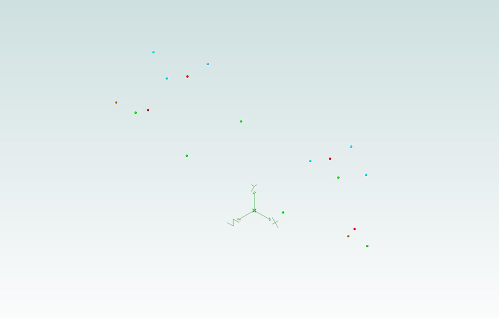
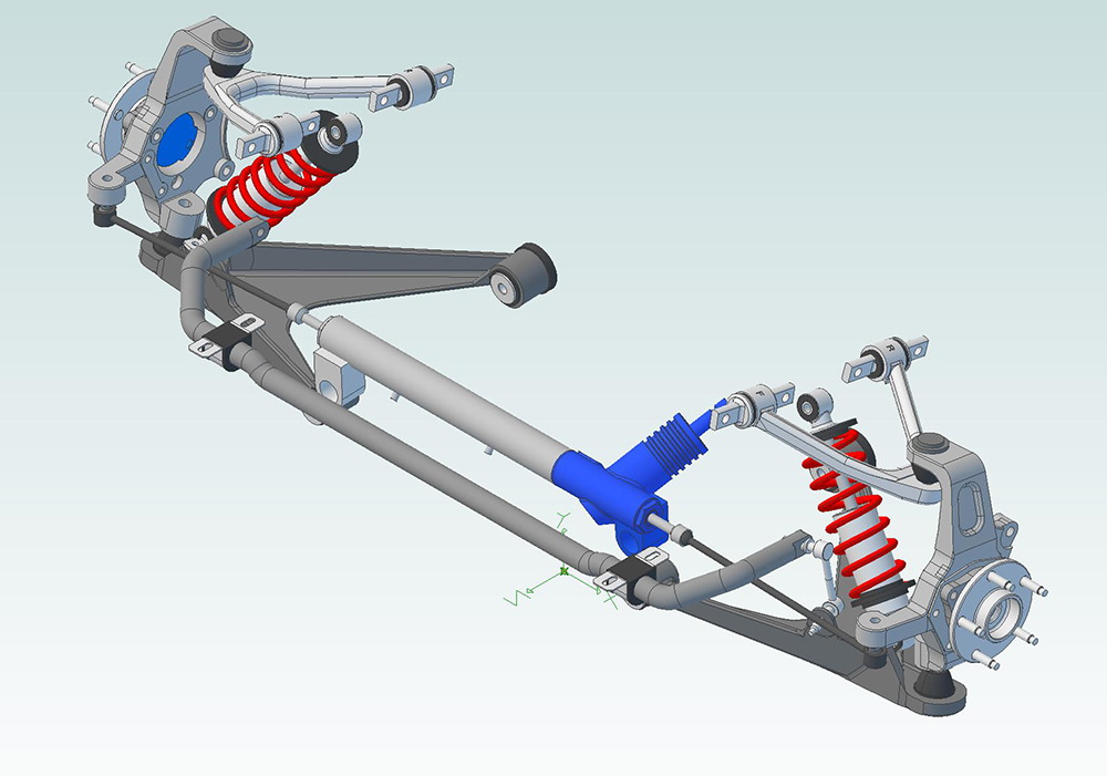
I then created 3D models of all of the suspension components and created a 3D solids model of my El Camino's suspension accurately locate in space according to the points calculated in the Performance Trends software. The first step was to insert locating points in the 3D software. The results of this are shown below in a front and top view. In this model:
- The three lower control arm points are shown in Green
- The Three upper control arm points are shown in Cyan
- The two coil over locating points are shown in Red.
- The outer Tie Rod end mounting points are shown in Orange (I did not locate the inner tie rod ends or Sway bar at this phase of the model.
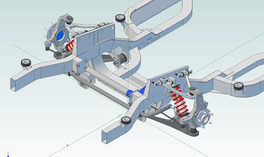
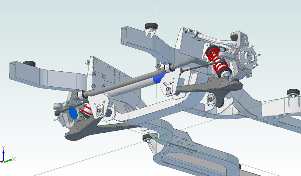
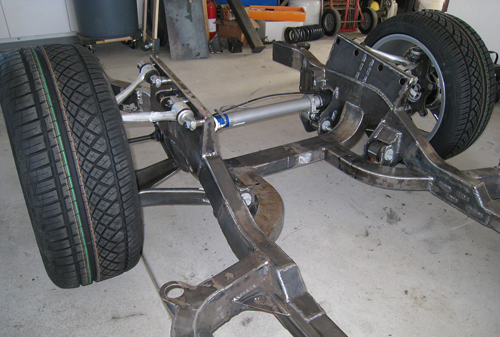
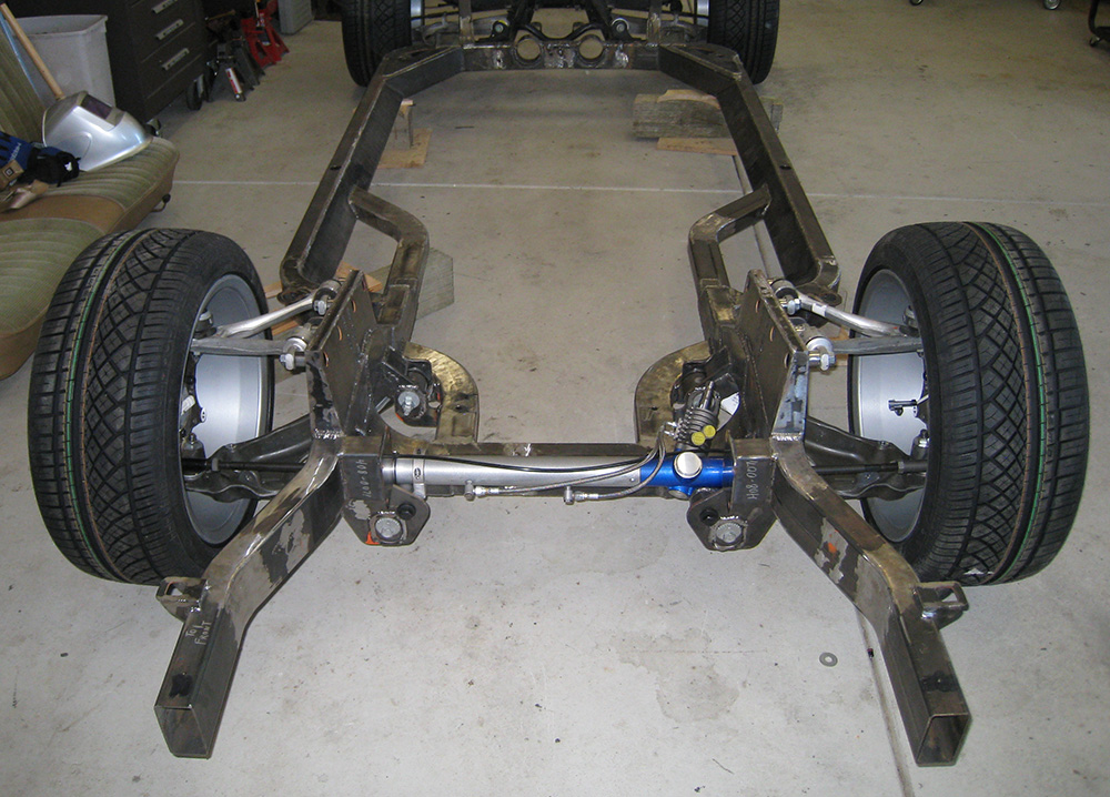
The next step was to connect all of the points to a frame structure. Designing a 3D solid model of a project does take a good bit of time, but the project can be "built", tested, modified, rebuilt, tweaked, etc on the screen before metal is cut. The payoff is that the real frame was simple to accurately assemble. Though you can't tell from the pictures below, the entire frame is built to within 1mm of what I designed.
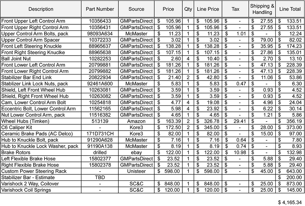
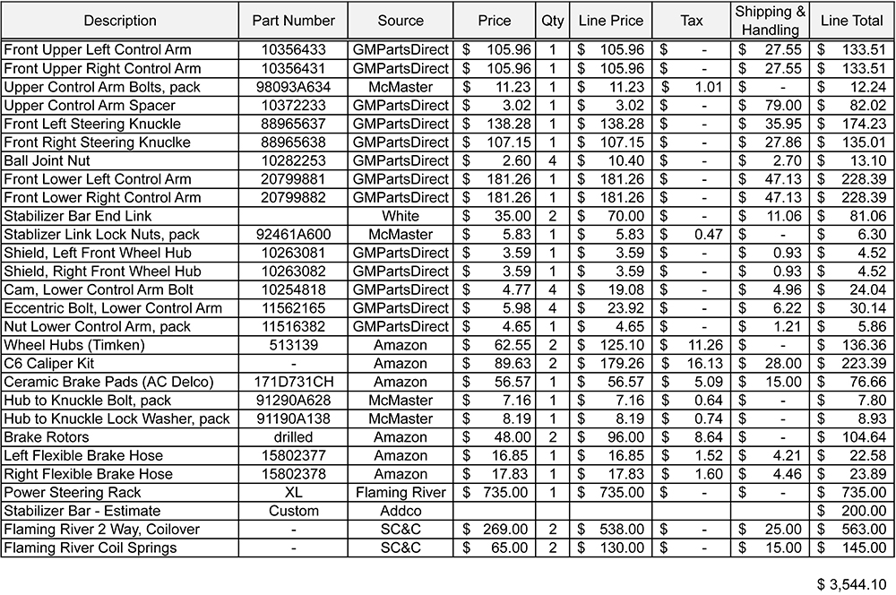
The amount of design and engineering necessarily to satisfactorily complete this effort was way more than I anticipated. Before I began, I anticipated that I would need to put about 250 hours into the design and fabrication of the entire suspension and frame. My actual time was almost 600 hours. If I were doing this professionally, I would be fired. But, I'm not. My cost estimates for the frame fared a bit better. Overall, the material cost was about $1,500. The cost increase was driven by the much larger number of water jet'd plates in the final design and my difficulty in getting a low cost shop to cut them for me. If I were doing this in any volume, the material cost would have been under $1,100. Looking at the estimated versus actual overall front suspension costs, yields the tables below.
Initial Estimate
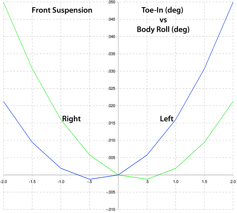
Below are some graphs of the calculated performance of the suspension. Some Highlights:
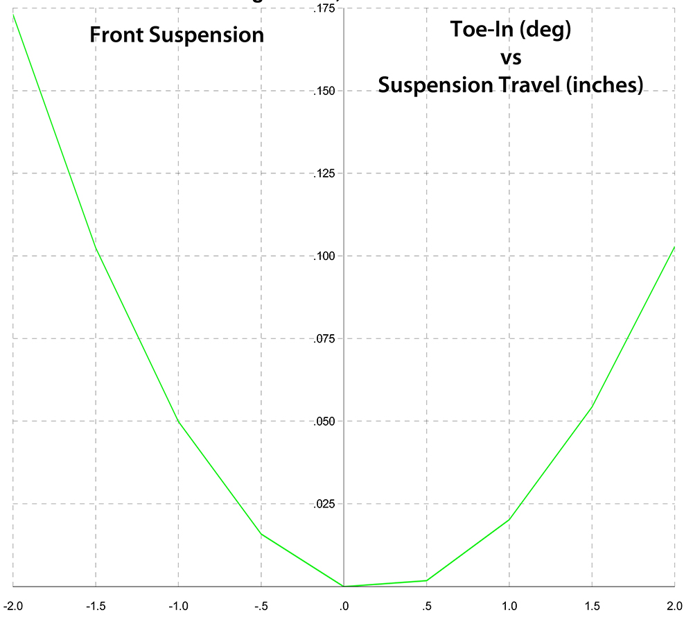
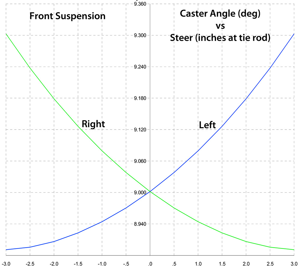
- Graph 2: Bump steer should be 0.17 degrees (or 1.0mm) over the expected suspension travel.
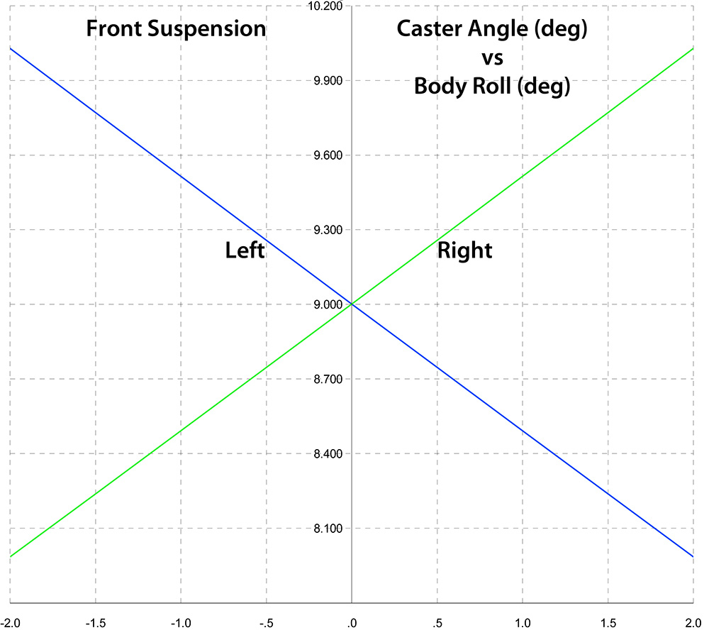
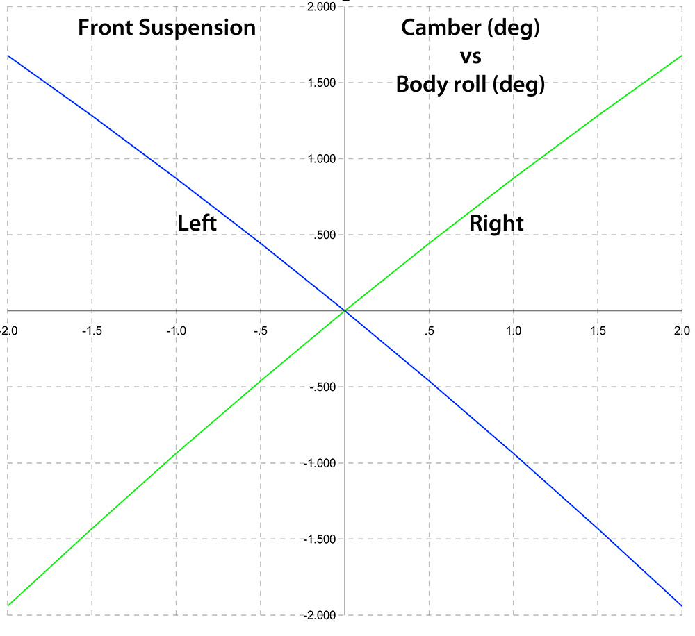
- Graph 7: Linear relationship between Camber and Body Roll
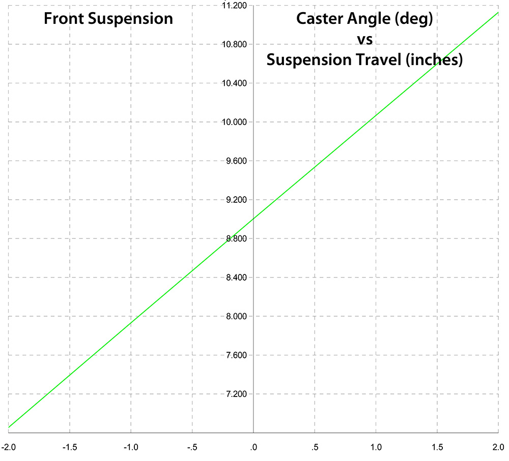
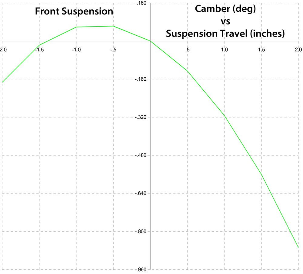
- Graph 8: Minimal Camber change with suspension travel
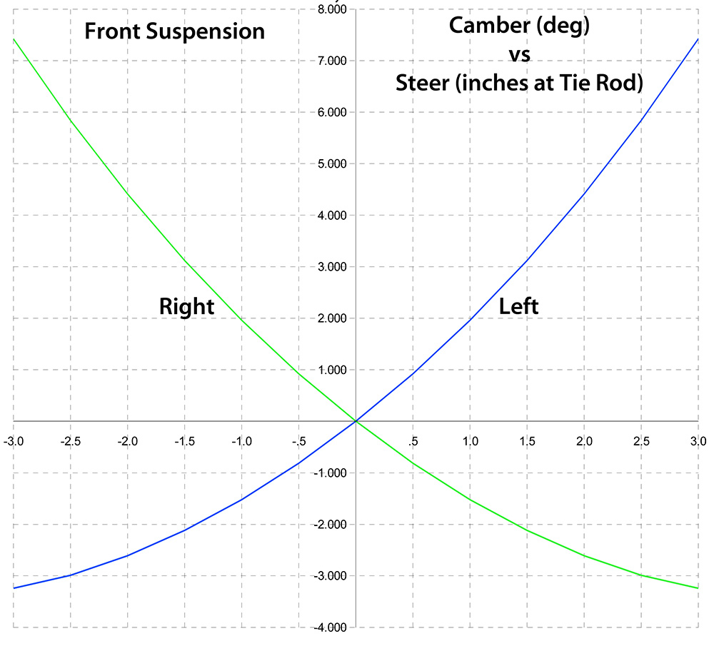
- Graph 9: Significant increase in Camber with larger steering inputs.
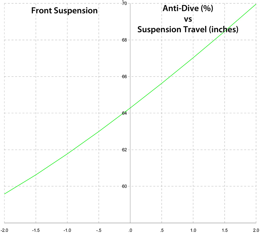
- Graph 10: Approximately 64% anti-dive. As importantly, the amount of anti-dive is increasing with spring compression, which will work to stabilize the chassis under hard braking.
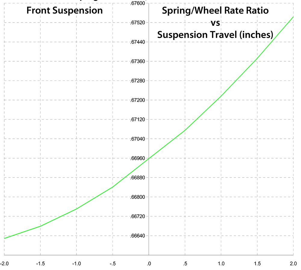
- Graph 11: Approximately a 1% change in wheel rate over the suspension travel

Front View
Top View
Isometric View
From this point, the front suspension component models were "installed" into the model and located by the reference points. As shown below.
Though I certainly did underestimate the amount of work, I am quite pleased with the calculated performance of the suspension and look forward to the results.
Actual Costs
In the Negative ledger: